
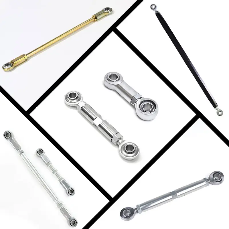
Performance Rearsets
Rearset changes often require a brake rod or pushrod that matches the new pedal location and master-cylinder position.
- Sportbike rearsets
- Rear brake pedal adjustment
- Replacement brake rods
- Model-specific geometry
Rear Brake Controls
Custom or relocated control assemblies may need a linkage with a specific center-to-center length, thread arrangement and connection style.
- Custom control layouts
- Master-cylinder pushrods
- Pedal reach and height
- Clearance around controls
OEM & Aftermarket Programs
Brands and rearset manufacturers may need repeatable linkage configurations developed from drawings, samples or reference parts.
- Custom-length assemblies
- Drawing-based production
- Replacement components
- Application-specific interfaces
Center-to-Center Length
The required length is determined by the pedal and master-cylinder attachment points. Existing linkage dimensions or a controlled drawing are useful references for development.
Interface
Rod-end, clevis, threaded pushrod and master-cylinder interfaces must match the surrounding components in thread, bore, pin and mounting orientation.
Locking Method
Once the required adjustment is established, threaded interfaces and lock nuts should be secured according to the application and installation instructions.
Pedal Position
Pedal height and reach affect rider ergonomics and the starting position of the control. Define the required pedal position together with the linkage length.
Articulation & Clearance
Check articulation through the full pedal movement. The linkage must not bind or interfere with the rearset, frame, exhaust, switch or other surrounding parts.
Post-installation checks
Use the motorcycle and rearset manufacturer’s procedure for final adjustment and verification.
- 01. Confirm pedal position and comfortable control reach.
- 02. Verify the specified brake pedal or pushrod free play.
- 03. Check brake-light switch operation after adjustment.
- 04. Check clearance, binding and fastener security.
| Configuration | Typical Use | Key Information |
|---|---|---|
| Rod-End Linkage | Articulated rearset and custom control assemblies | Rod-end type, bore, thread and misalignment space |
| Threaded Brake Rod | Adjustable connection between pedal and control point | Length, thread size, thread direction, locking method |
| Pushrod & Clevis | Master-cylinder actuation with a clevis-type connection | Pushrod end, pin interface, travel and alignment |
| Custom Assembly | OEM, replacement or application-specific programs | Drawing, sample, existing linkage and motorcycle information |
Exact dimensions, materials, finishes and available production options should be confirmed against the application before quotation.
Drawing-Based Production
Use controlled drawings to define the linkage length, interface geometry and critical dimensions for the application.
Sample & Reference Parts
Existing linkages and reference components can help establish fitment requirements when a drawing is not available.
Application-Specific Configuration
Production follows the approved drawing, sample or application-specific dimensions so the required linkage geometry and interfaces can be maintained across the production program.
Motorcycle Make / Model / Year
Identify the motorcycle platform.
Rearset / Control System
Brand, model and configuration.
Existing Linkage or Drawing
Provide a sample, photo or controlled dimensions.
Center-to-Center Length
Existing or required linkage dimension.
Interface / Thread Details
Rod end, clevis, pin, thrad or other connection.
Rear Master Cylinder Information
Model, connection and mounting context where available.
Photos of the Installed Assembly
Show the pedal, linkage and surrounding control layout.
Build the Linkage Around the Brake-Control Geometry.
Tell us which motorcycle, rearset and master cylinder you are working with. We will review the required dimensions and configuration for your application.